
Everything Oryx CAD does lives in one place: the ORYX tab of Blender's side panel. Set two things first, and the rest of the workflow follows. Tout ce que fait Oryx CAD tient au même endroit : l'onglet ORYX du panneau latéral de Blender. Réglez deux choses d'abord, le reste du workflow suit.
1 Open the panel & set the languageOuvrir le panneau & régler la langue FR / EN toggle, top of the Oryx panelBascule FR / EN, en haut du panneau Oryx
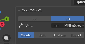
Oryx CAD adds one tab to Blender's side panel. From it you reach the whole plugin and its four working tabs: Create, Edit, Analyze, Export. The FR / EN toggle at the top switches every label in the panel between French and English instantly. Oryx CAD ajoute un onglet au panneau latéral de Blender. De là, vous atteignez tout le plugin et ses quatre onglets de travail : Create, Edit, Analyze, Export. La bascule FR / EN en haut change instantanément toutes les étiquettes du panneau.
- Press N in the 3D viewport, then click the ORYX tab on the right edge.Touche N dans la vue 3D, puis cliquez l'onglet ORYX sur le bord droit.
- At the top, click FR or EN to choose the panel language.En haut, cliquez FR ou EN pour choisir la langue du panneau.
- The change is immediate, every label, button and message in the panel updates.Le changement est immédiat, chaque étiquette, bouton et message du panneau se met à jour.
2 Set the unit to millimetresRégler l'unité en millimètres Unit dropdown, just below the language toggleMenu Unit, juste sous la bascule de langue
Oryx CAD is metric-first. The Unit dropdown sets the scene to millimetres so every tool, every dimension and every export speaks in real-world sizes: 1 Blender unit = 1 mm. Oryx CAD est métrique d'abord. Le menu Unit règle la scène en millimètres pour que chaque outil, chaque dimension et chaque export parle en tailles réelles : 1 unité Blender = 1 mm.
- Click the Unit dropdown, just under the FR / EN toggle.Cliquez le menu Unit, juste sous la bascule FR / EN.
- Choose mm, Millimetres. Every measurement, screw dimension and exported file now uses millimetres.Choisissez mm, Millimètres. Chaque mesure, dimension de vis et fichier exporté utilise désormais le millimètre.
- Do this once per scene, before using any other tool.Faites-le une fois par scène, avant d'utiliser un autre outil.
3 The four working tabsLes quatre onglets de travail Create · Edit · Analyze · ExportCreate · Edit · Analyze · Export
Below the language and unit controls sit four tabs, the four stages of building a real, printable part. This documentation is organised exactly the same way, one section per tab. Sous les réglages de langue et d'unité se trouvent quatre onglets, les quatre étapes d'une vraie pièce imprimable. Cette documentation est organisée de la même façon, une section par onglet.
Create is where parts are born: parametric gears, real ISO hardware you can snap straight onto a face with Position, then Alignment and Shape Drilling to fit any parts together. Create, c'est là que naissent les pièces : engrenages paramétriques, vraie visserie ISO que vous pouvez poser directement sur une face avec Position, puis Alignment et Shape Drilling pour assembler n'importe quelles pièces.
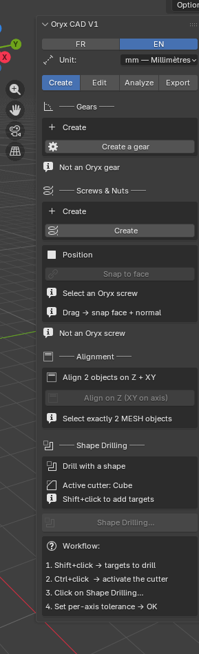
1 Gears (Gear Engine)Gears (Gear Engine) Parametric spur gears, mesh-accurate pairsEngrenages droits paramétriques, paires qui s'engrènent vraiment
The Gear Engine generates real spur gears from standard module/teeth/pressure-angle parameters, the same numbers a mechanical drawing would use. Set a tooth count and module once, and a mating gear at the correct centre distance is one click away. Gear Engine génère de vrais engrenages droits à partir des paramètres standards module/dents/angle de pression, les mêmes valeurs qu'un plan mécanique. Réglez un nombre de dents et un module, et l'engrenage complémentaire à la bonne distance d'entraxe n'est qu'à un clic.
- Open Create → Gears. Set Z (tooth count) and Module, these two drive the whole gear.Ouvrez Create → Gears. Réglez Z (nombre de dents) et Module, ces deux valeurs pilotent tout l'engrenage.
- Adjust Pressure angle, Face width and Bore diameter to match your shaft and design.Ajustez Pressure angle, Face width et Bore diameter selon votre axe et votre design.
- Add a Keyway if the gear needs to be locked to its shaft.Ajoutez un Keyway (rainure de clavette) si l'engrenage doit être bloqué sur son axe.
- Click Generate. To create a matching gear, set Mating gear diam., Oryx computes the correct Centre distance automatically.Cliquez Generate. Pour créer l'engrenage complémentaire, réglez Mating gear diam., Oryx calcule automatiquement le bon Centre distance.
2 Screws & Nuts (ISO Hardware)Screws & Nuts (ISO Hardware) Real ISO fasteners, with real helical threadsVraie visserie ISO, avec de vrais filetages hélicoïdaux
Generates standard ISO screws and nuts from real catalogue presets, M3 to M12 and beyond, with the correct head shape, length and pitch. Unlike most Blender bolt generators, the thread itself can be a real helical surface, not just a texture, so it prints and assembles like the real part. Génère de la visserie ISO standard à partir de vrais presets de catalogue, M3 à M12 et plus, avec la bonne forme de tête, longueur et pas. Contrairement à la plupart des générateurs de boulons pour Blender, le filetage lui-même peut être une vraie surface hélicoïdale, pas juste une texture, donc il s'imprime et s'assemble comme la vraie pièce.
- Open Create → Screws & Nuts and choose an ISO preset (e.g. M5), it fills in diameter and pitch automatically.Ouvrez Create → Screws & Nuts et choisissez un ISO preset (ex. M5), diamètre et pas se remplissent automatiquement.
- Pick a Head type (hex, socket, countersunk…) and set Total length.Choisissez un Head type (hexagonal, BTR, fraisé…) et réglez Total length.
- Fine-tune Head diameter / Head height if you need a non-standard head.Affinez Head diameter / Head height pour une tête non standard.
- Click Generate. To tweak afterwards, change any value and click Modify & recreate, the part rebuilds in place.Cliquez Generate. Pour ajuster après coup, changez une valeur puis cliquez Modify & recreate, la pièce se reconstruit en place.
3 PositionPosition Snap an Oryx screw or nut onto a face, aligned to its normalPose une vis ou un écrou Oryx sur une face, aligné à sa normale SoonBientôt
Position is part of the Screws & Nuts workflow: it takes a screw or nut created with ISO Hardware and drops it directly onto a chosen face of another object, automatically rotated so its axis follows that face's normal. No manual rotating, no eyeballing the angle. It applies to hardware only, gears are placed by hand like any other object. Position fait partie du workflow Screws & Nuts : il prend une vis ou un écrou créé avec ISO Hardware et le pose directement sur une face choisie d'un autre objet, automatiquement orienté selon la normale de cette face. Plus de rotation manuelle, plus d'angle approximatif. Il s'applique uniquement à la visserie, les engrenages se placent à la main comme n'importe quel objet.
- Create the screw or nut you want to position, from Create → Screws & Nuts.Créez la vis ou l'écrou à positionner, depuis Create → Screws & Nuts.
- Open Create → Position and follow the prompt to pick a target face on another mesh.Ouvrez Create → Position et suivez l'invite pour choisir une face cible sur un autre maillage.
- The screw or nut snaps to that face's centre and rotates to align with the face normal.La vis ou l'écrou se cale sur le centre de cette face et s'oriente selon sa normale.
4 AlignmentAlignment Align two mesh objects on Z, or Z + XYAligne deux objets sur Z, ou Z + XY SoonBientôt
Alignment lines up two mesh objects, either matching their height on the Z axis only (sit one on top of the other), or fully centring them on Z + XY (stack them concentrically). A fast way to mate two parts before a Boolean or a Clean Merge. Alignment aligne deux objets, soit en faisant correspondre leur hauteur sur l'axe Z seul (poser l'un sur l'autre), soit en les centrant complètement sur Z + XY (les superposer de façon concentrique). Une façon rapide d'accoupler deux pièces avant un Boolean ou un Clean Merge.
- Select the object to move, then shift-select the reference object (the active one stays put).Sélectionnez l'objet à déplacer, puis ajoutez l'objet de référence (l'objet actif ne bouge pas).
- Open Create → Alignment and choose Z for height-only, or Z + XY to also centre on the horizontal plane.Ouvrez Create → Alignment et choisissez Z pour la hauteur seule, ou Z + XY pour aussi centrer sur le plan horizontal.
- The selected object snaps into alignment with the reference.L'objet sélectionné se cale sur la référence.
5 Shape DrillingShape Drilling Drill a hole the exact shape of any objectPerce un trou à la forme exacte de n'importe quel objet
Shape Drilling cuts a hole through one object using the exact silhouette of another, your cutter. The cutter can be anything: a cylinder for a bolt clearance hole, a hex prism for a nut trap, or a custom shape for a connector cutout. The panel always shows which object is the active cutter before you commit. Shape Drilling perce un trou à travers un objet en utilisant la silhouette exacte d'un autre, votre cutter. Le cutter peut être n'importe quoi : un cylindre pour un trou de passage de vis, un prisme hexagonal pour un logement d'écrou, ou une forme personnalisée pour un connecteur. Le panneau affiche toujours quel objet est le cutter actif avant validation.
- Position the cutter object where the hole should go, and check it points the right direction.Positionnez l'objet cutter là où le trou doit être, et vérifiez son orientation.
- Select the cutter, then shift-select the target object (the one to be drilled).Sélectionnez le cutter, puis ajoutez l'objet cible (celui à percer).
- Open Create → Shape Drilling, the panel confirms which object is the Active cutter.Ouvrez Create → Shape Drilling, le panneau confirme quel objet est l'Active cutter.
- Follow the on-screen Workflow steps to confirm and run the drill, the cutter's shape is subtracted from the target.Suivez les étapes du Workflow affiché pour confirmer et lancer le perçage, la forme du cutter est soustraite de la cible.
Edit is where two parts become one assembly: stretch to a target size, snap surfaces together with pixel-perfect precision, fix origins, and clean up topology, by hand or by preset. Edit, c'est là où deux pièces deviennent un assemblage : étirer à une taille cible, accoler des surfaces avec une précision parfaite, corriger les origines, et nettoyer la topologie, à la main ou par preset.
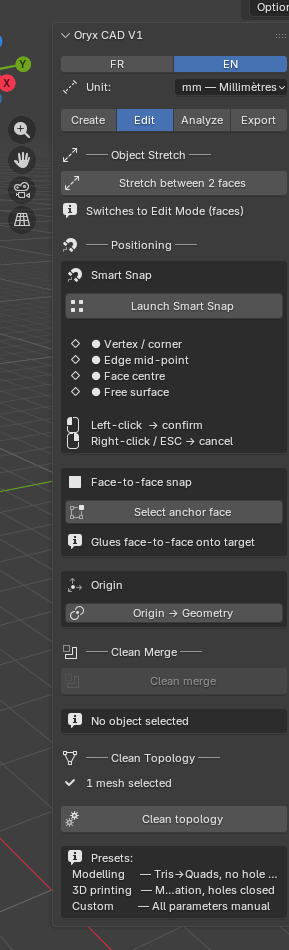
1 Object StretchObject Stretch Resize an object to an exact dimension on one axisRedimensionne un objet à une dimension exacte sur un axe
Object Stretch scales an object along a single axis until it reaches an exact target length, in millimetres, without distorting the other two axes. It's the difference between "scale roughly to fit" and "make this exactly 50 mm long". Object Stretch redimensionne un objet sur un seul axe jusqu'à atteindre une longueur cible exacte, en millimètres, sans déformer les deux autres axes. C'est la différence entre « mettre à l'échelle à peu près » et « rendre cette pièce exactement à 50 mm ».
- Select the object you want to resize.Sélectionnez l'objet à redimensionner.
- Open Edit → Object Stretch and choose the axis (X, Y or Z) to stretch along.Ouvrez Edit → Object Stretch et choisissez l'axe (X, Y ou Z) à étirer.
- Enter the target length for that axis in millimetres.Saisissez la longueur cible pour cet axe en millimètres.
- Confirm, the object scales on that axis only, until it measures exactly the value you typed.Confirmez, l'objet s'échelle sur cet axe seulement, jusqu'à mesurer exactement la valeur saisie.
2 Smart SnapSmart Snap Snap an object onto a vertex, edge, face or surface pointAligne un objet sur un sommet, une arête, une face ou un point de surface
Smart Snap moves the active object's origin (and the object with it) to a precise point on another mesh, picked live in the viewport. It recognises four kinds of target as you hover: a vertex / corner, an edge mid-point, a face centre, or any free point on a surface. Smart Snap déplace l'origine de l'objet actif (et l'objet avec elle) vers un point précis d'un autre maillage, choisi en direct dans la vue 3D. Il reconnaît quatre types de cible au survol : un sommet / coin, le milieu d'une arête, le centre d'une face, ou un point libre sur une surface.
- Select the object you want to move, then click Launch Smart Snap in Edit → Smart Snap.Sélectionnez l'objet à déplacer, puis cliquez Launch Smart Snap dans Edit → Smart Snap.
- Hover over the target mesh, Oryx highlights the nearest vertex, edge mid-point, face centre, or free surface point.Survolez le maillage cible, Oryx surligne le sommet, milieu d'arête, centre de face ou point libre le plus proche.
- Left-click to snap the object there and confirm. Right-click at any time to cancel and leave the object where it was.Clic gauche pour caler l'objet et confirmer. Clic droit à tout moment pour annuler et laisser l'objet où il était.
3 Face-to-face snapFace-to-face snap Glue one object's face flush onto another's faceColle une face d'un objet à plat sur une face d'un autre
Face-to-face snap takes a face on the active object, your anchor face, and glues it perfectly flat onto a face on the target object: same plane, same orientation, no gap, no overlap. Ideal for mating two printed parts along a flat seam. Face-to-face snap prend une face de l'objet actif, votre face d'ancrage, et la colle parfaitement à plat sur une face de l'objet cible : même plan, même orientation, sans jeu ni chevauchement. Idéal pour assembler deux pièces imprimées sur une jonction plane.
- Select the object to move, then open Edit → Face-to-face snap and click Select anchor face.Sélectionnez l'objet à déplacer, puis ouvrez Edit → Face-to-face snap et cliquez Select anchor face.
- Click the face on your object that should end up against the other part.Cliquez la face de votre objet qui doit se retrouver contre l'autre pièce.
- Click the matching face on the target object, the panel confirms it glues face-to-face onto target.Cliquez la face correspondante sur l'objet cible, le panneau confirme qu'il colle face contre face sur la cible.
- The active object moves and rotates so the two faces sit flush, ready for a Clean Merge or a Boolean.L'objet actif se déplace et tourne pour que les deux faces soient à plat l'une contre l'autre, prêt pour un Clean Merge ou un Boolean.
4 Origin → GeometryOrigin → Geometry Recentre an object's origin on its actual geometryRecentre l'origine d'un objet sur sa géométrie réelle SoonBientôt
Many of the snap and alignment tools work relative to an object's origin. If an object was moved, duplicated or imported with its origin off in space, those tools behave unpredictably. Origin → Geometry recentres the origin to the middle of the object's actual geometry in one click. Plusieurs outils de snap et d'alignement travaillent par rapport à l'origine d'un objet. Si un objet a été déplacé, dupliqué ou importé avec une origine décalée dans l'espace, ces outils deviennent imprévisibles. Origin → Geometry recentre l'origine au milieu de la géométrie réelle de l'objet, en un clic.
- Select the object whose origin looks wrong (often visible as the orange dot sitting away from the mesh).Sélectionnez l'objet dont l'origine semble décalée (souvent visible comme le point orange éloigné du maillage).
- Open Edit → Origin → Geometry and click the button, the origin jumps to the geometric centre of the mesh.Ouvrez Edit → Origin → Geometry et cliquez le bouton, l'origine se replace au centre géométrique du maillage.
5 Clean MergeClean Merge Combine multiple objects into one watertight meshCombine plusieurs objets en un seul maillage étanche
Clean Merge combines two or more overlapping or touching objects into a single mesh, and cleans up the seam: duplicate vertices welded, internal faces removed, normals fixed. The result is a single watertight object, ready for Diagnostic and export. Clean Merge combine deux objets ou plus qui se touchent ou se superposent en un seul maillage, et nettoie la jonction : sommets dupliqués fusionnés, faces internes supprimées, normales corrigées. Le résultat est un seul objet étanche, prêt pour Diagnostic et l'export.
- Position the parts so they overlap or touch where they should be joined, use Alignment, Smart Snap or Face-to-face snap first if needed.Positionnez les pièces pour qu'elles se touchent ou se superposent à l'endroit voulu, utilisez d'abord Alignment, Smart Snap ou Face-to-face snap si besoin.
- Select all the objects to combine, then open Edit → Clean Merge.Sélectionnez tous les objets à combiner, puis ouvrez Edit → Clean Merge.
- If nothing is selected, the panel shows "No object selected", select your parts first.Si rien n'est sélectionné, le panneau affiche « No object selected », sélectionnez d'abord vos pièces.
- Click Clean Merge, the objects become one, with the seam welded clean.Cliquez Clean Merge, les objets deviennent un seul, la jonction est nettoyée et soudée.
6 Clean TopologyClean Topology Retopologise with Modelling, 3D printing or custom presetsRetopologie avec presets Modelling, 3D printing ou personnalisé SoonBientôt
Clean Topology rebuilds a mesh's surface with cleaner, more even geometry, without changing its shape. Three presets cover the most common needs: Modelling (smooth, edit-friendly topology), 3D printing (lighter, slicer-friendly meshes), and Custom for your own density and settings. Clean Topology reconstruit la surface d'un maillage avec une géométrie plus propre et régulière, sans changer sa forme. Trois presets couvrent les besoins courants : Modelling (topologie lisse, facile à éditer), 3D printing (maillages plus légers, adaptés au slicer), et Custom pour votre propre densité et réglages.
- Select the mesh to clean up, the panel confirms "1 mesh selected".Sélectionnez le maillage à nettoyer, le panneau confirme « 1 mesh selected ».
- Open Edit → Clean Topology and choose a preset: Modelling, 3D printing, or Custom.Ouvrez Edit → Clean Topology et choisissez un preset : Modelling, 3D printing, ou Custom.
- With Custom, adjust the density settings to taste, then run the preset to rebuild the mesh.Avec Custom, ajustez la densité selon vos besoins, puis lancez le preset pour reconstruire le maillage.
Before you export, Analyze tells you the truth about your mesh: is it watertight, how heavy is it, where are the problems, and exactly how big are its features. Two tools, one tab. Avant d'exporter, Analyze vous dit la vérité sur votre maillage : est-il étanche, quel est son poids, où sont les problèmes, et quelles sont les dimensions exactes de ses éléments. Deux outils, un onglet.
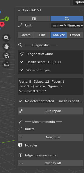
1 Diagnostic & SmartRepair™Diagnostic & SmartRepair™ Health score, mesh report, one-click repairScore de santé, rapport de maillage, réparation en un clic
Diagnostic reads the active mesh and gives it a health score: vertex, edge, face, triangle, quad and n-gon counts, the enclosed volume, and whether the mesh is watertight (no holes, ready to print). If it finds problems, SmartRepair™ fixes the common ones, non-manifold edges, loose geometry, flipped normals, in one click. It's deterministic: same mesh in, same fix out, no AI guessing. Diagnostic analyse le maillage actif et lui donne un score de santé : nombre de sommets, arêtes, faces, triangles, quads et n-gons, le volume intérieur, et si le maillage est étanche (sans trou, prêt à imprimer). En cas de problème, SmartRepair™ corrige les cas courants, arêtes non-manifold, géométrie isolée, normales inversées, en un clic. C'est déterministe : même maillage en entrée, même correction en sortie, sans aléa d'IA.
- Select the object you want to check, then open Analyze → Diagnostic.Sélectionnez l'objet à vérifier, puis ouvrez Analyze → Diagnostic.
- Read the report: Health score at the top, then Watertight, and the full geometry breakdown below.Lisez le rapport : Health score en haut, puis Watertight, et le détail complet de la géométrie en dessous.
- If the score flags issues, click Run repair. SmartRepair™ applies its fixes and the report refreshes.Si le score signale des problèmes, cliquez Run repair. SmartRepair™ applique ses corrections et le rapport se rafraîchit.
- Re-check Watertight, once it's green, the mesh is safe to export.Revérifiez Watertight, une fois au vert, le maillage est prêt à exporter.
2 Measurements & rulersMesures & règles Live edge readout, on-screen rulersLecture d'arête en direct, règles à l'écran
Two ways to see real-world dimensions directly in the viewport. Edge measurements overlays the length of every edge of the active mesh, instantly, no clicking required. Rulers let you drop persistent measurement markers between any two points, useful for checking a specific clearance or fit. Deux façons de voir les dimensions réelles directement dans la vue 3D. Edge measurements affiche la longueur de chaque arête du maillage actif, instantanément, sans rien cliquer. Rulers permet de placer des repères de mesure persistants entre deux points, utile pour vérifier un jeu ou un ajustement précis.
- Select your object, then toggle Edge measurements on, every edge length appears as an overlay.Sélectionnez votre objet, puis activez Edge measurements, la longueur de chaque arête s'affiche en surimpression.
- For a specific dimension, click + New ruler and click two points in the viewport, the distance appears live as you move.Pour une dimension précise, cliquez + New ruler puis cliquez deux points dans la vue, la distance s'affiche en direct pendant le déplacement.
- Add as many rulers as you need, they stay until you remove them or click Overlay off.Ajoutez autant de règles que nécessaire, elles restent jusqu'à suppression ou jusqu'à Overlay off.
- Overlay off hides every measurement at once, for a clean screenshot or render.Overlay off masque toutes les mesures d'un coup, pour une capture ou un rendu propre.
The last step: get your part out of Blender in the format your slicer or CAD tool expects, in millimetres, either the whole scene or just what's selected. La dernière étape : sortir votre pièce de Blender dans le format attendu par votre slicer ou logiciel de CAO, en millimètres, soit toute la scène, soit juste la sélection.
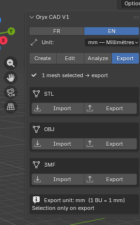
1 Export & import: STL / OBJ / 3MFExport & import: STL / OBJ / 3MF One block per format, each with its own Import and ExportUn bloc par format, chacun avec son Import et son Export
The Export tab has one block for each of the three formats Oryx CAD speaks: STL (printing), OBJ (general 3D), and 3MF (modern slicers, keeps more metadata). Each block has its own Import and Export buttons, so you choose the exact format both ways, no generic "export 3D file" dialog to second-guess. L'onglet Export a un bloc pour chacun des trois formats parlés par Oryx CAD : STL (impression), OBJ (3D générale), et 3MF (slicers modernes, conserve plus de métadonnées). Chaque bloc a ses propres boutons Import et Export, vous choisissez donc le format exact dans les deux sens, sans dialogue générique « export 3D » à deviner.
- Select the object(s) ready to export, the panel shows "1 mesh selected → export" (or the relevant count) once something is active.Sélectionnez le ou les objets prêts à exporter, le panneau affiche « 1 mesh selected → export » (ou le nombre correspondant) dès qu'un objet est actif.
- Open Export → STL / OBJ / 3MF and click Export in the block matching the format you need.Ouvrez Export → STL / OBJ / 3MF et cliquez Export dans le bloc correspondant au format voulu.
- To bring a file back in, use the Import button in the matching format block.Pour réimporter un fichier, utilisez le bouton Import du bloc du format correspondant.
2 Quick export & selection-onlyQuick export & selection-only Millimetre-locked, export just what you've selectedVerrouillé en millimètres, exporte uniquement votre sélection
Two small details at the bottom of the Export tab quietly do a lot of work. Export unit: mm (1 BU = 1 mm) guarantees every exported file uses the same millimetre scale you designed in, set on the Start tab. Selection only on export means you don't have to hide or delete the rest of your scene, just select the part you want and export, everything else is ignored. Deux petits détails en bas de l'onglet Export font discrètement tout le travail. Export unit: mm (1 BU = 1 mm) garantit que chaque fichier exporté utilise la même échelle millimétrique que celle de votre conception, réglée dans l'onglet Start. Selection only on export signifie que vous n'avez pas besoin de cacher ou supprimer le reste de la scène, sélectionnez juste la pièce voulue et exportez, le reste est ignoré.
- Keep your scene as-is, reference geometry, multiple parts, whatever you need while working.Gardez votre scène telle quelle, géométrie de référence, plusieurs pièces, tout ce dont vous avez besoin pendant le travail.
- When ready, select only the part you want to send to your printer or CAD tool.Une fois prêt, sélectionnez uniquement la pièce à envoyer vers votre imprimante ou logiciel de CAO.
- Click Export on the format you need, only the selection is written to the file, at the correct millimetre scale.Cliquez Export sur le format voulu, seule la sélection est écrite dans le fichier, à la bonne échelle millimétrique.